The trigger system of the LHCb detector has several levels. The level 0 and level 1 triggers are implemented
in hardware and investigate only a small part of the data collected by the LHCb Detector.
After these first two trigger levels, the whole detector is read out by the
Data Acquisition System and the data needs to be passed through the read-out network to the
LHCb Event Filter Farm, where the additional trigger levels 2 and 3 are performed
in software. These trigger levels include the entire data collected by the detector in
their evaluation of an event.
Figure 1 - The LHCb DAQ system architecture
More specifically, after event-fragments have been collected by the Read-out Units (RU),
they are passed through the Read-out Network (RN) in such a way that all data belonging
to one particular event reaches one specific Sub-Farm Controller (SFC).
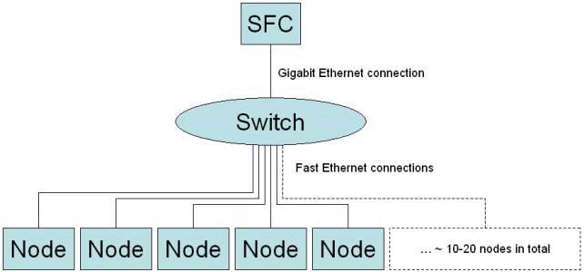
There will be ~ 25-30 sub-farms, each containing a Sub-Farm Controller (SFC)
and ~ 10-20 PCs or "nodes". Any data traffic from or to the nodes has to go through
and is controlled by the SFC of the sub-farm.
A SFC therefore receives multiple segments of data belonging to the same event. It assembles
them and reorders them forming an event data-structure, which now contains all the data collected
about the actual event. This process is called "Event-building".
After a SFC has built a new event it will pass it on to exactly one of its nodes. The node receiving
a new event will perform the level 2 and 3 trigger algorithms and, if the event is accepted,
it will write back the processed event data to permanent storage.
As usual, this data traffic goes through the SFC as well.
Figure 2 - Sub-farm architecture
Figure 2 shows the architecture of the sub-farms. The SFC is connected to a switch, which links it
to its nodes. The link between the SFC and the switch is a Gigabit Ethernet connection
(unidirectional nominal throughput: 1000 Mbit/s). The links between the switch and each of the
sub-farms are fast Ethernet connection (nominal throughput per link: 100 Mbit/s).
Each SFC should support the forwarding of events at ~ 80 Mbyte/s (640 Mbit/s).
Notice that this implies an incoming data traffic of 80 Mbyte/s and an outgoing
traffic of 80 Mbyte/s at the same time.
It is necessary to analyze the performance of Gigabit Ethernet Network Interface Cards,
in the way they will be used in the sub-farms of the LHCb Data Acquisition system.
This involves studying the impact of PCI bus-systems, tuning parameters like IRQ coalescence
and frame length as well as evaluating the performance difference between TCP and UDP.
The aim is to investigate the experimentally achievable throughput of Gigabit Ethernet Links
in order to have a reference value for the load-balancing experiments that follow.
Load-balancing:
In the LHCb DAQ sub-farms, the sub-farm controllers will receive events that have to be
passed on to their nodes for processing. A node will then analyze the event using the
level 2 and 3 trigger algorithms. This processing takes time, and the SFC therefore
has to distribute the events more or less evenly between its nodes in such a way that
the nodes have time to process their event(s) without falling behind too much.
This process of distributing the computational load between several PCs is called
"load-balancing".
Different possible load-balancing algorithms such as "round-robin" and
an algorithm using control tokens are available. Their advantages and disadvantages
need to be compared and different implementation possibilities have to be investigated.
Lawrence Besaw, "Berkeley UNIX System Calls and Interprocess Communication",
January 1987, Revised September 1987 and January 1991 by Marvin Solomon
[pdf]
"Carrier Sense multiple access with collision detection (CSMA/CD)
access method and physical layer specifications" (aka Ethernet) IEEE Standard 802.3 (2000 version)
This page was last edited by Wulf Thannhaeuser on
September 24, 2002.