This page collects various design guide-lines and recommendations for board-designers implementing a CC-PC. It will be constantly updated. Please mail niko.neufeld@cern.ch about anything you find incorrect, incomplete or missing. EthernetEach board hosting a CC-PC must provide an Ethernet connection.
The CC-PCs will be connected to the ECS network via 100BaseT Ethernet (a.k.a as
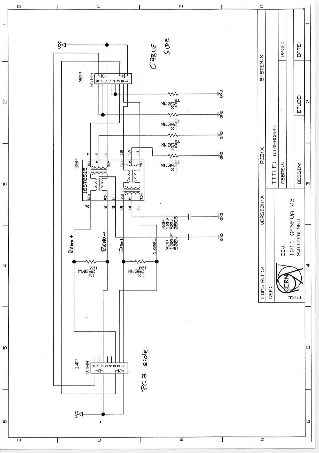
"copper-based" Fastethernet). We have verified two connector / magnetics combinations, which work with the i82559/CC-PC 1.) An RJ-45 connector with integrated magnetic
filtering: 2.) A
discreet magnetic filtering device: Pin-Out of the LHCb ConnectorMost changes to the pin-out of the LHCb Specific connector to the PLX PCI9030 (datasheet and Errata) interface chip between PCI and the local bus. This chip has a different set of control signals to the Local bus and hence this had to be reflected in the pins of the connector. We tried to re-use control signals as much as possible, so that existing designs wouldn't break. Find the final pin-out of the glue-card
here (the old
pin-out is still here
for comparison).
An explanation for the changes in the pin-out can be found under
this web-page. The glue-card connector to the CC-PC includes all signals which need to be routed between CC-PC and glue-card. Its definition is here. Other minor changes concern JTAG. On the new board the JTAG producing circuitry (emulating a ByteBlaster cable) will be supplied by a voltage which is taken from the carrier board and this will determine the signaling level of the output JTAG. Like this the implementer can choose the Level of JTAG between 3.3 and 5 Volts. This feature will most likely disappear in future versions of the glueboard, since the Chip envisaged to fan-out JTAG to different JTAG chains can ONLY run at 3.3 Volts. Dimensions of the LHCb Glue-Card (2nd Prototype)The dimensions and connector locations of the LHCb Glue-Card v2.0 can be found here. The final prototype (currently under test) might have slightly different dimensions, but we will do our utmost that the connector locations are not changed. The mechanical dimensions and the connector locations can be found here. While there might be slight changes in the future on the board itself, the dimensions and connector locations should not change anymore. CC-PC Board connectorThe following connector is needed to hold a CC-PC on the board: We have some of these connectors and can provide you with small quantities. If you need any or even better have a good source please write to lhcb-ecs@cern.ch PowerFrom the datasheet it is not completely obvious that the CC-PC needs only 5.0 V power supply. The 3.3 V at pin A91 and B91 of J2 are actually outputs (to be used with care, for a total of ~ 1 A). This is made clear in the integration manual V1.6 (section 4.2.5, page 36). The 3.3 V for the core voltage of the CC-PC are generated internally, and will make the D31 LED go on (or at least should, we have seen CC-PCs where this is not the case, although they work!). RS232 - serial port (COM0)The CC-PC does not generate the correct levels for the serial port. An additional chip is needed, e.g. the MAX211 (datasheet), which is included on the LHCb Glue-Card. Important: If you do not intend to use the serial port, i.e. you do not have the MAX211 RS232 or equivalent, then you need 4.7k pull-ups respectively pull-downs on the four signals: CTS1-, DCD1-, DSR1-, RX1 and RI1- Failing to do so might halt the CC-PC in the POST (POwerupSelfTest) sequence of the BIOS before the graphics card is initialised - your screen will stay black... Information for specific pins: clarifications, FAQ etcUnder this heading information concerning specific pins is collected. This information is drawn from experience or from Digital Logic's support
Evaluation Board & reference design:Schematics of the test-board for the final glue-card are available here
Please send comments and suggestions to niko.neufeld@cern.ch. |
|||||||||||||||||||||||||
